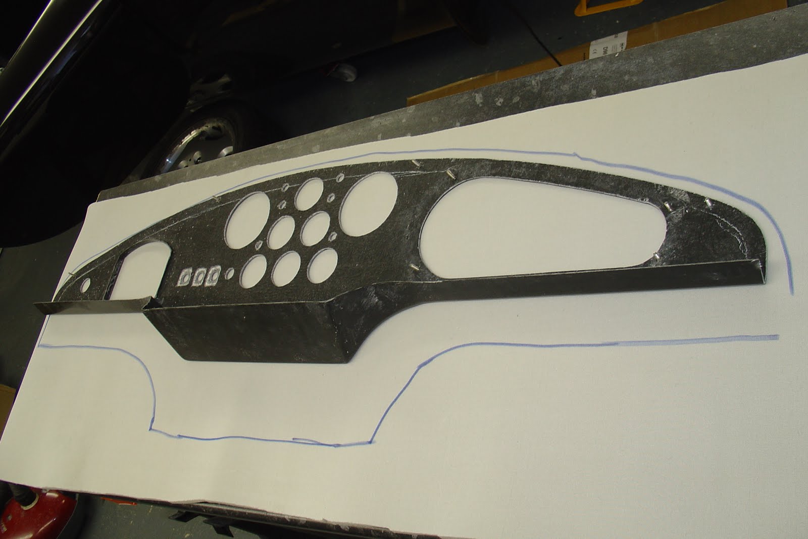
I checked the marked holes and a couple were marked a little bit bigger than I worked out, so I remarked them. Checked they were all central to the body and each other by offering the dash up in the cockpit and all was spot on.

Next was to cut out the holes, I would have used a hole saw but have suffered with it wondering in the past on various things, so opted for the trusty dremel and a tile cutting bit. easy to use and with a hoover next to it you can get real close and detailed.

The small lamp holes were cut out with a step drill to 12mm then opened to 12.5 with a normal drill bit on reverse so as not to dig in or chip the edges.
Same process with the start button and switches.

The switches, if using Lucas type, need recessing on the back so enough thread can poke through for the retaining nut.

Now for the foam. Sprayed adhesive onto the dash face and the foam with the fabric face taking the glue. Laid the dash on top and cut out the holes.
 Took the foam round the bottom edges.
 While I was in this far, I attempted some leather work. Another first.
As my dash curves down in the centre, the bit of leather supplied follows this line quite nicely. But is a little tricky getting it wrinkle free around that bit. Thinking of it as 3 sections made it easier to approach
It seemed to work best by gluing the bottom middle bit first with the seam lined up and then glue the top of the middle.

I didn't pull it too tight but enough to take any wrinkles out. Then work the tops L/H and R/H, pulling the sides if needed to remove any wrinkles.
 Lastly the bottom sides were pulled and glued, snipping the curved edge as you would when folding the dial holes in.
That's enough for today.
2 comments:
Steve,
On the fourth picture down, there is a line drawn on the back of the dash at equal distance from the edge which appears to be a reference mark for the warning lights, is that correct and can you give me the measurememt ?
Thanks
Ryan
The white line is where the lip of the scuttle return sits. I marked this from behind to see what needs clearing for dials into the return edge. Only now spotted I need to make clearance for the lights.
reference marks were spotted on the face by GD.
Post a Comment